QR Code / Data Matrix generator for Altium
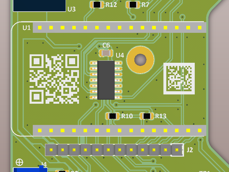
Generation of the QR Code or the Data Matrix
Enter the text in the field below. It can be a multi-line text. Choose the options, then click on the generate button. This will display a preview of the 2D code. If you are happy with the result, press the copy button, this will put the needed CSV data needed for Altium Designer in the clipboard. Else press the new button and change the options.
For QR codes, the ECC define the level of redundancy and so the tolerance to read errors (even the lowest one, i.e. L, is usually ok on PCBs). The quiet zone is the margin around the 2D code, needed for a correct reading (2 dots is usually a good choice).
You can also choose the polarity of the 2D code. I prefer black dots as overlay, but some scanners are unable to read them as it looks like a negative Data Matrix or QR Code (Data Matrix scanners seem more picky on that).
Note that it is expected that Altium is set to work in mm. If you are working in mils, change temporarly to mm (press Q) before importing the 2D code.
Inclusion on the PCB
Note: you can click on the screenshots below to zoom in.
In Altium Designer, first open the "PCB List" window (Shift+F12):
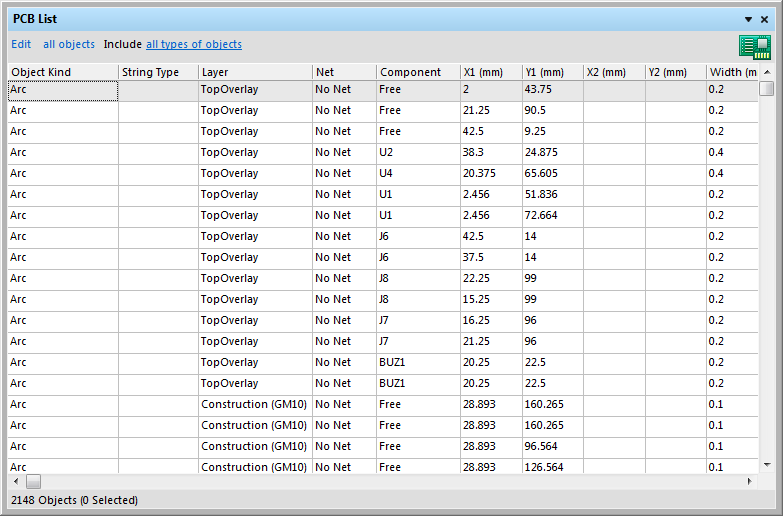
Check on top left of the window that it is in edit mode. If it is in view mode, click on the "view" text to change it.
Then right click and select "Smart Grid Insert" or type Ctrl-Ins. This will open the following dialog:
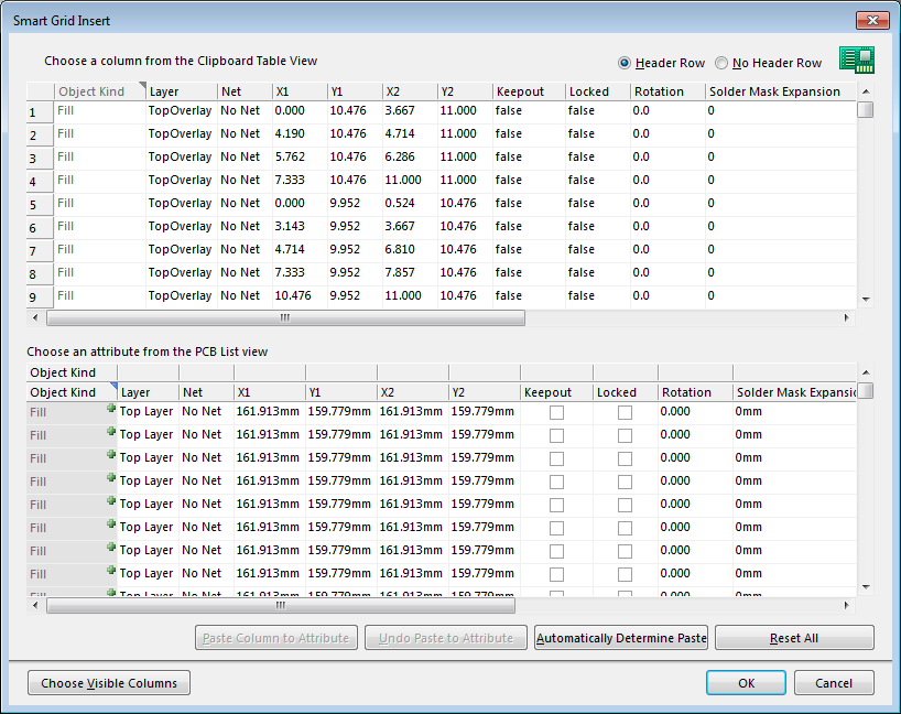
Click on "Automatic Determine Paste", this shall copy the clipboard data (upper table) to the attribute table:
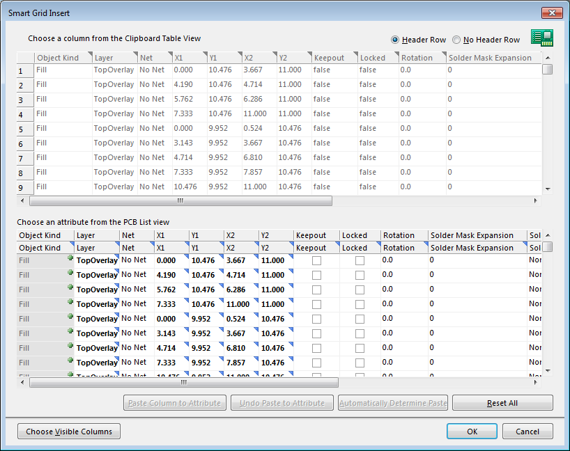
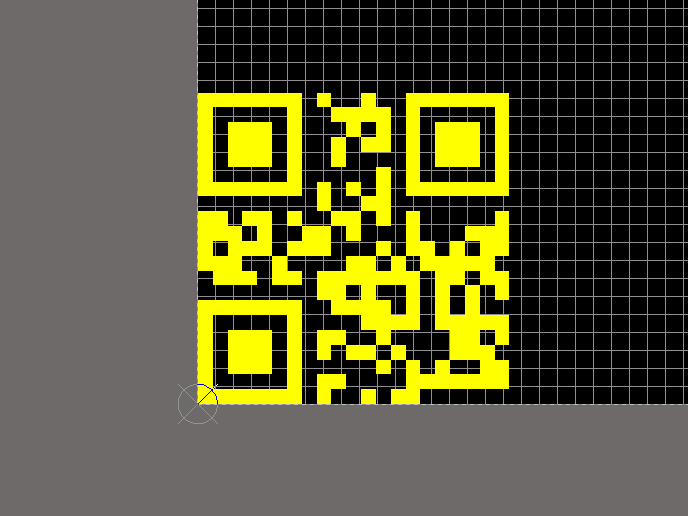
Click on the "OK" button. You shall now see the QR Code or Data Matrix on your PCB. It is composed of a lot of fills. I recommend that you select all these elements and create an union so you can move the QR Code or Datamatrix without problem.
That's all. If this tool helps you in your day-to-day work, consider making a small donation on Paypal, look for the yellow "donate" button. It will help to pay for the web hosting costs.
Comments
(Most recent first)Do you know which is the minimum qr-code size readable? ( 20mm, 5mm, 10 mm?) I'm going to perform some tests, but if you have any information they are highly appreciated
PS: maybe i was doing things wrongly, but the first time i had the altium grid set to mils instead of mm and i couldn't find the qr code (eventhough it was set to 20mm). As soon as i switched to mm unit on altium i had no trouble.
many thanks!
It generates the QR code but does not allow the insertion of the code into the PCB
But AD19 don't work with your method. Delite objects