Baseboard for NodeMCU V2

While experimenting with the NodeMCU ESP8266 module, I quickly realized that during experimentation it is not practical to connect peripheral modules directly to the NodeMCU pins using Dupont wires. I often needed to connect several devices in parallel (I2C for example) as well as being able to probe the signals with a scope or a logic analyzer.
Looking in AliExpress or eBay, I was not able to find a breakout board designed for the NodeMCU V2. One exists for the v3, but as the size is different it is not usable for me.
So I decided to design one. As I wanted to test the low cost PCB manufacturing services of JLCPCB, this was a good opportunity.
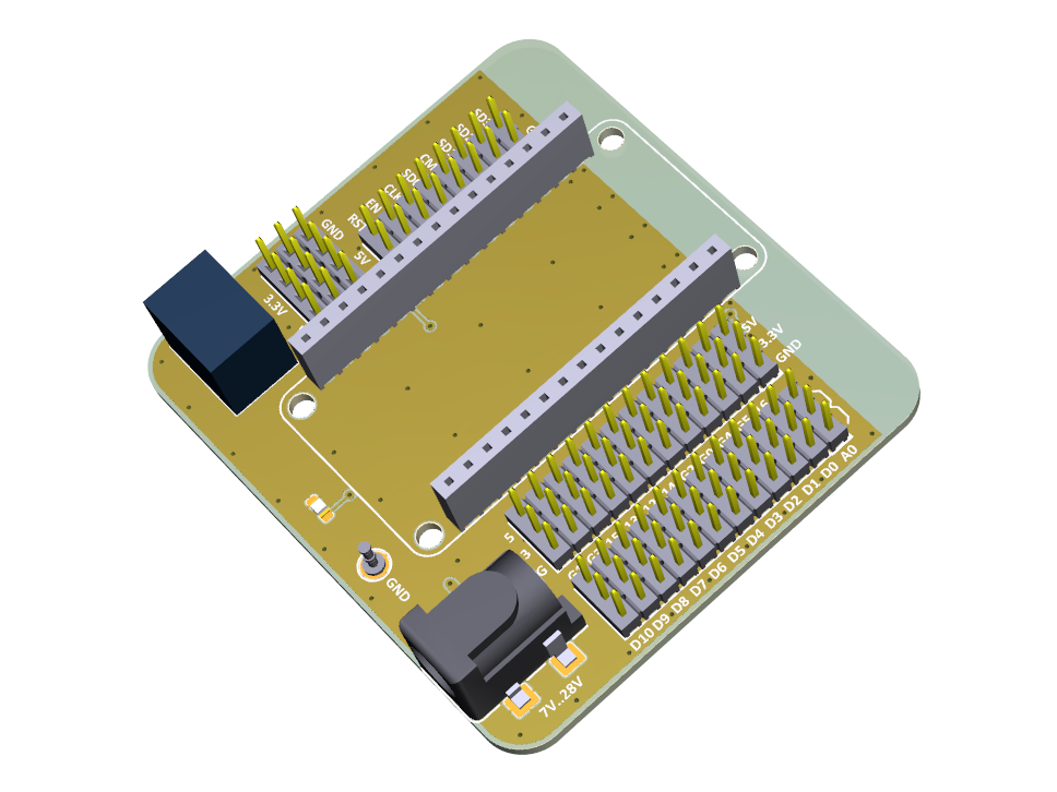
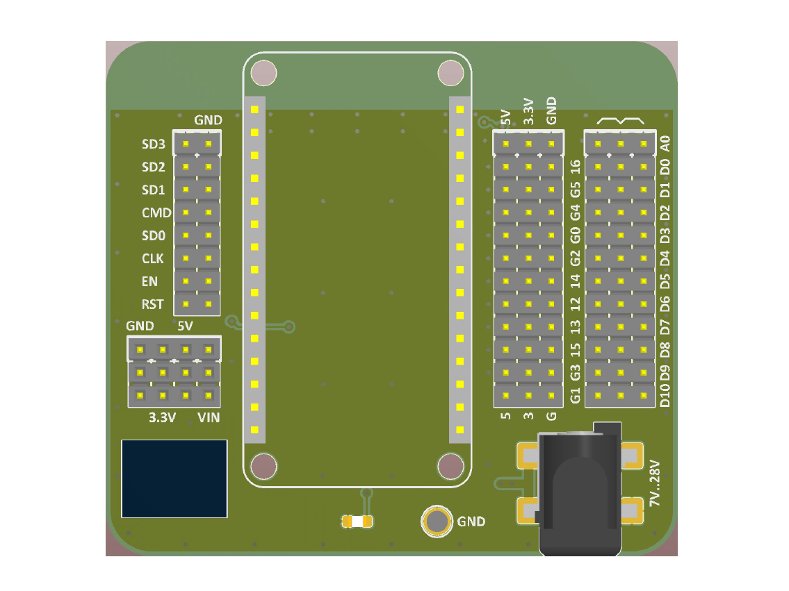
The result is a small board with a lot of redundant connections:

First of all GPIO D0 to D10, as well as analog input A0, are replicated on 3 header pins. So it is now easy to connect two I2C devices in parralel with logic analyzer probes.
Then I added plenty of 3.3V, 5V and GND pins, to be able to easily power several peripheral modules.
I also put the remaining pins on a seperate header. I didn't replicate them on several pins, as they are usually not usable for the user's application.
Finally, I added a low cost Recom 5V DC/DC converter, as the NodeMCU doesn't make the 5V USB power available on its pins, but I needed 5V to power some of my external modules.
Detailed project documentation can be downloaded in PDF.
Data for production of the PCB (gerber and drill) is available as a ZIP.
Comments
(Most recent first)Currently no comments for the current topic.